STK401-060
SANYO Electric Co., Ltd. Semiconductor Business Headquarters
TOKYO OFFICE Tokyo Bldg., 1-10, 1 Chome, Ueno, Taito-ku, TOKYO, 110 JAPAN
10997HA(ID) / 71696HA(ID) / 41495TH(ID) No. 4680--1/8
Ordering number: EN 4680B
Thick Film Hybrid IC
AF Power Amplifier (Split Power Supply)
(35W + 35W min, THD = 0.4%)
Overview
The STK401-060 is a thick-film audio power amplifier IC
belonging to a series in which all devices are pin compati-
ble. This allows a single PCB design to be used to con-
struct amplifiers of various output capacity simply by
changing hybrid ICs. Also, this series is part of a new,
larger series that comprises mutually similar devices with
the same pin compatibility. This makes possible the devel-
opment of a 2-channel amplifier from a 3-channel ampli-
fier using the same PCB. In addition, this new series
features 6/3
drive in order to support the low impedance
of modern speakers.
Features
∑ Pin compatible
STK400-000 series (3-channel/single package)
STK401-000 series (2-channel/single package)
∑
Output load impedance R
L
= 6/3
supported
∑ New pin configuration
Pin configuration has been grouped into individual
blocks of inputs, outputs and supply lines, minimizing
the adverse effects of pattern layout on operating char-
acteristics.
∑ Few external components
In comparison with existing series, external bootstrap
resistors and capacitors can be eliminated.
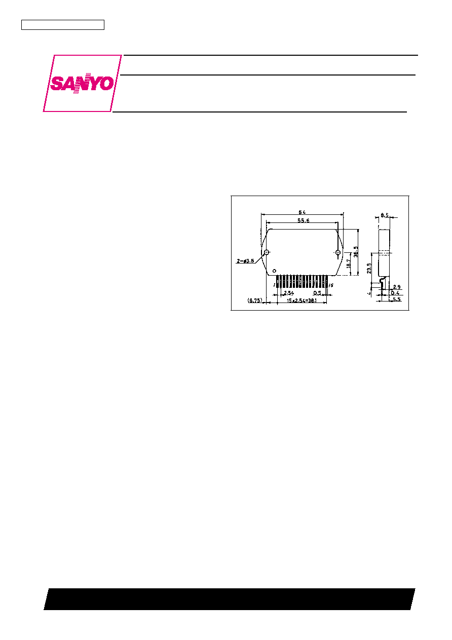
Package Dimensions
unit: mm
4134
[STK401-060]
STK401-060
No. 4680--2/8
Specifications
Maximum Ratings
at Ta = 25
∞
C
Operating Characteristics
at Ta = 25
∞
C, R
L
= 6
(noninductive load), Rg = 600
, VG = 40dB
Notes.
All tests are measured using a constant-voltage supply unless otherwise specified.
Available time for load short-circuit and output noise voltage are measured using the transformer supply specified below.
The output noise voltage is the peak value of an average-reading meter with an rms value scale (VTVM). A regulated AC supply (50Hz) should be used to eliminate the
effects of AC primary line flicker noise.
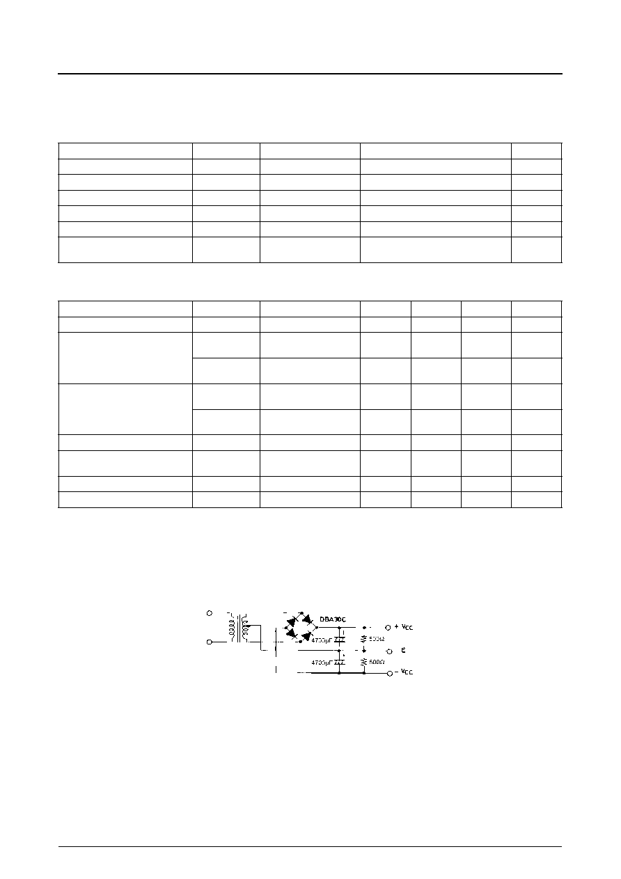
Specified Transformer Supply (RP-25 or Equivalent)
Parameter
Symbol
Conditions
Ratings
Unit
Maximum supply voltage
V
CC
max
±
41
V
Thermal resistance
j-c
Per power transistor
1.8
∞
C/W
Junction temperature
Tj
150
∞
C
Operating substrate temperature
Tc
125
∞
C
Storage temperature
Tstg
-
30 to +125
∞
C
Available time for load short-circuit
t
s
V
CC
=
±
28V, R
L
= 6
,
f = 50Hz, P
O
= 35W
1
s
Parameter
Symbol
Conditions
min
typ
max
Unit
Quiescent current
I
CCO
V
CC
=
±
34V
20
60
100
mA
Output power
P
O
(1)
V
CC
=
±
28V, f = 20Hz to
20kHz, THD = 0.4%
35
40
≠
W
P
O
(2)
V
CC
=
±
23V, f = 1kHz,
THD = 1.0%, R
L
= 3
35
40
≠
W
Total harmonic distortion
THD(1)
V
CC
=
±
28V, f = 20Hz to
20kHz, P
O
= 1.0W
≠
≠
0.4
%
THD(2)
V
CC
=
±
28V, f = 1kHz,
P
O
= 5.0W
≠
0.01
≠
%
Frequency response
f
L
, f
H
V
CC
=
±
28V, P
O
= 1.0W,
≠
20 to 50k
≠
Hz
Input impedance
r
i
V
CC
=
±
28V, f = 1kHz,
P
O
= 1.0W
≠
55
≠
k
Output noise voltage
V
NO
V
CC
=
±
34V, Rg = 10k
≠
≠
1.2
mVrms
Neutral voltage
V
N
V
CC
=
±
34V
-
70
0
+70
mV
+0
-
3
dB
STK401-060
No. 4680--3/8
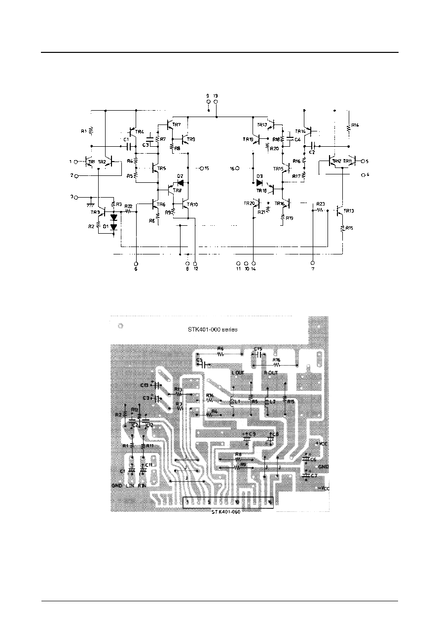
Equivalent Circuit
Sample PCB Layout for 2-Channel or 3-Channel Amplifiers
Copper (Cu) foil surface
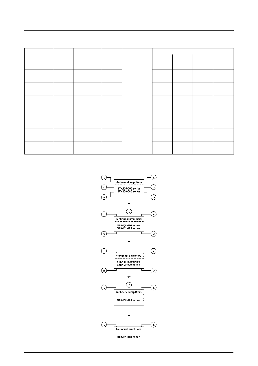
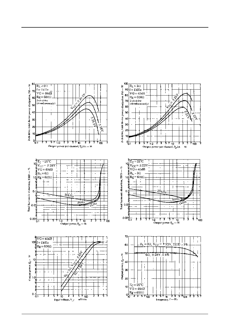
Pin 6 of STK400-000 series devices corresponds to pin 1 of STK401-000 series devices.
STK401-060
No. 4680--4/8
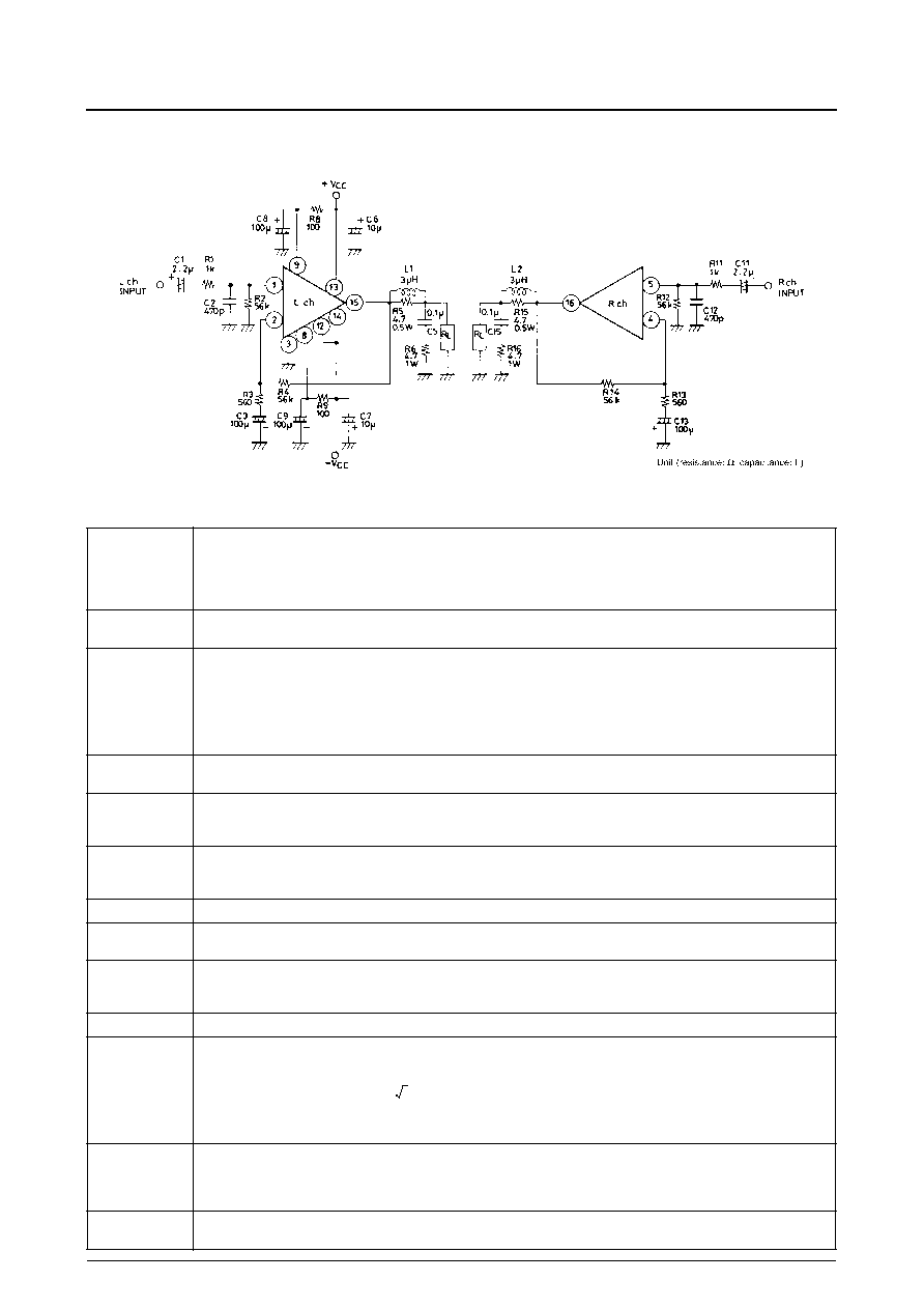
Sample Application Circuit
External Component Description
C1, C11
Input coupling capacitors.
For DC blocking. Since capacitor reactance becomes larger at lower frequencies, the output noise can be adversely affected by signal source
resistance-dependent 1/f noise. In this case, a lower reactance value should be chosen. In order to remove pop noise at power-on, larger
values of capacitance should be chosen for C1 and C11, which determine the input time constant, and smaller values for C3 and C13 in the
NF circuit.
C2, C12
Input filter capacitors.
These, together with R1 and R11, form filters to reduce high-frequency noise.
C3, C13
NF capacitors.
These determine the low-side cut-off frequency.
Large values should be chosen for C3 and C13 to maintain voltage gain at low frequencies. However, because this would tend to increase the
shock noise at power-on, values larger than absolutely necessary should be avoided.
C5, C15
Oscillation prevention capacitors.
Mylar capacitors are recommended for their excellent thermal and frequency characteristics.
C6, C7
Oscillation prevention capacitors.
These should be inserted as close as possible to the IC supply pins to reduce supply impedance and hence provide stable IC operation.
Electrolytic capacitors are recommended.
C8, C9
Decoupling capacitors.
These, together with R8 and R9, form time constant circuits that remove shock noise and ripple voltage from the supply, preventing any noise
being coupled to the inputs.
R1, R11
Input filter resistors.
R2, R12
Input bias resistors.
These are used to bias the input pins at zero potential. The input impedance is largely determined by this resistance.
R3, R13
R4, R14
Voltage-gain VG setting resistors.
VG = 40dB is recommended using R3, R13 = 560
, and R4, R14 = 56k
. Gain adjustments are best made using R3 and R13. If gain
adjustments are made using R4 and R14, then set R2, R12 = R4, R14 to maintain V
N
balance stability.
R5, R15
Oscillation prevention resistors.
R6, R16
Oscillation prevention resistors.
The power dissipated in these resistors is dependent on the frequency, as given below.
where f is the output signal frequency upper limit.
R8, R9
Ripple filter resistors.
P
O
max, ripple rejection and supply power-on shock noise are all affected by this resistance. These resistors should be chosen taking into
consideration both the function they perform as predriver transistor limiting resistors during load short circuits and the peak current that flows
through them when charging C8 and C9.
L1, L2
Oscillation prevention coils.
These correct the phase difference caused by capacitive loads and increase stability against oscillation.
f
L
1
2
C
3
C
13
(
)
R
3
R
13
(
)
◊
◊
-----------------------------------------------------------------
=
P
R6(R16)
V
CC
max
2
/
1 2
f
/
C
5
C
15
(
)
◊
R
6
R
16
(
)
+
---------------------------------------------------------------------------
2
R
6
◊
R
16
(
)
=
STK401-060
No. 4680--5/8
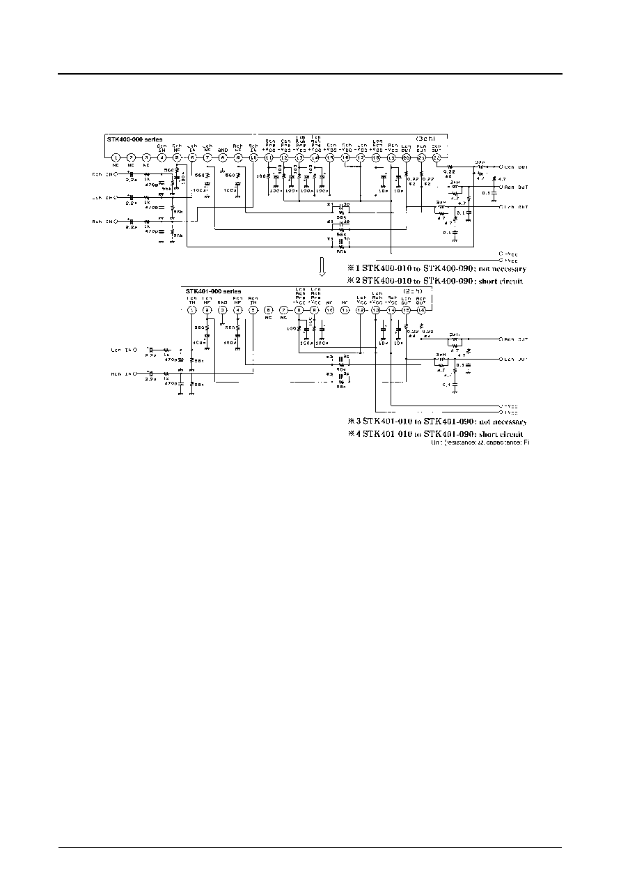
Series Configuration
Sample Designs using a Common PCB
1. V
CC
max1 (R
L
= 6
), V
CC
max2 (R
L
= 3 to 6
), V
CC
1 (R
L
= 6
), V
CC
2 (R
L
= 3
)
3-channel
amplifier type
Nos.
Rated
output
2-channel
amplifier type
Nos.
Rated
output
THD [%]
f = 20Hz to 20kHz
Supply voltage [V]
1
V
CC
max1
V
CC
max2
V
CC
1
V
CC
2
STK400-010
10W
◊
3
STK401-010
10W
◊
2
0.4
≠
±
26
±
17.5
±
14
STK400-020
15W
◊
3
STK401-020
15W
◊
2
≠
±
29
±
20
±
16
STK400-030
20W
◊
3
STK401-030
20W
◊
2
≠
±
34
±
23
±
19
STK400-040
25W
◊
3
STK401-040
25W
◊
2
≠
±
36
±
25
±
21
STK400-050
30W
◊
3
STK401-050
30W
◊
2
≠
±
39
±
26
±
22
STK400-060
35W
◊
3
STK401-060
35W
◊
2
≠
±
41
±
28
±
23
STK400-070
40W
◊
3
STK401-070
40W
◊
2
≠
±
44
±
30
±
24
STK400-080
45W
◊
3
STK401-080
45W
◊
2
≠
±
45
±
31
±
25
STK400-090
50W
◊
3
STK401-090
50W
◊
2
≠
±
47
±
32
±
26
STK400-100
60W
◊
3
STK401-100
60W
◊
2
≠
±
51
±
35
±
27
STK400-110
70W
◊
3
STK401-110
70W
◊
2
±
56.0
≠
±
38
≠
≠
≠
STK401-120
80W
◊
2
±
61.0
≠
±
42
≠
≠
≠
STK401-130
100W
◊
2
±
65.0
≠
±
45
≠
≠
≠
STK401-140
120W
◊
2
±
74.0
≠
±
51
≠
STK401-060
No. 4680--6/8
External Circuit Diagram
Heatsink Design Considerations
The heatsink thermal resistance,
c-a, required to dissipate
the STK401-060 device total power dissipation, Pd, is
determined as follows:
Condition 1: IC substrate temperature not to exceed
125
∞
C.
Pd
◊
c-a + Ta < 125
∞
C ........................................ (1)
where Ta is the guaranteed maximum ambient tempera-
ture.
Condition 2: Power transistor junction temperature, Tj, not
to exceed 150
∞
C.
Pd
◊
c-a + Pd/N
◊
j-c + Ta < 150
∞
C ................. (2)
where N is the number of power transistors and
j-c is the
power transistor thermal resistance per transistor. Note
that the power dissipated per transistor is the total, Pd,
divided evenly among the N power transistors.
Expressions (1) and (2) can be rewritten making
c-a the
subject.
c-a < (125
-
Ta)/Pd ............................................. (1)
c-a < (150
-
Ta)/Pd
-
j-c/N .............................. (2)
The heatsink required must have a thermal resistance that
simultaneously satisfies both expressions.
The heatsink thermal resistance can be determined from
(1)
and (2)
once the following parameters have been
defined.
∑ Supply voltage, V
CC
∑ Load resistance, R
L
∑ Guaranteed maximum ambient temperature, Ta
The total device power dissipation when STK401-060
V
CC
=
±
28V and R
L
= 6
, for a continuous sine wave sig-
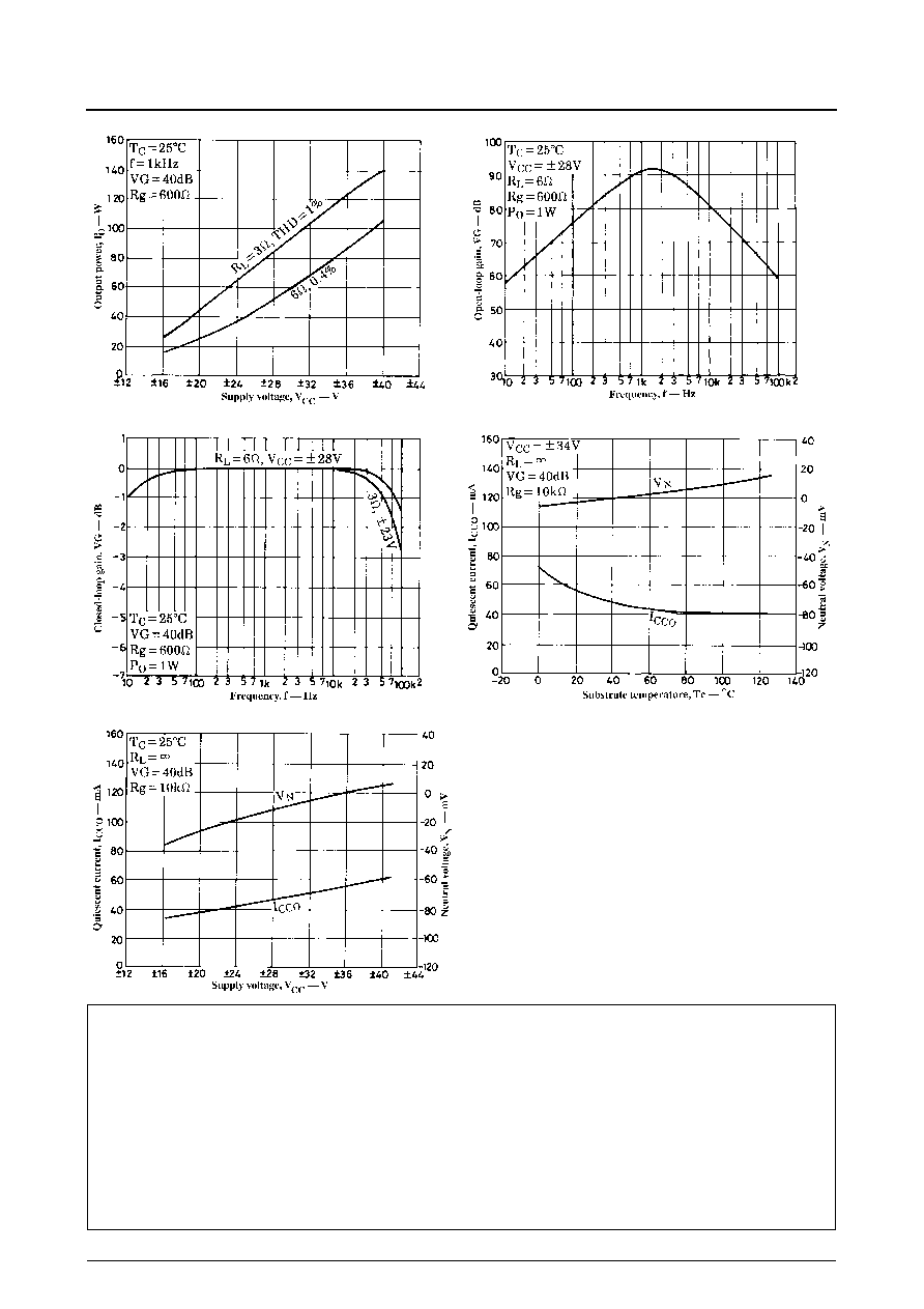
nal, is a maximum of 54W, as shown in Figure 1.
When estimating the power dissipation for an actual audio
signal input, the rule of thumb is to select Pd correspond-
ing to 1/10 P
O
max (within safe limits) for a continuous
sine wave input. For example, from Figure 1,
Pd = 32.4W (for 1/10 P
O
max = 3.5W)
The STK401-060 has 4 power transistors, and the thermal
resistance per transistor,
j-c, is 1.8
∞
C/W. If the guaran-
teed maximum ambient temperature, Ta, is 50
∞
C, then the
required heatsink thermal resistance,
c-a, is:
From expression (1)
:
c-a < (125
-
50)/32.4
< 2.31
From expression (2)
:
c-a < (150
-
50)/32.4
-
1.8/4
< 2.63
Therefore, to satisfy both expressions, the required heat-
sink must have a thermal resistance less than 2.31
∞
C/W.
STK401-060
No. 4680--7/8
Similarly, when STK401-060 V
CC
=
±
23V and R
L
= 3
,
from Figure 2:
Pd = 38W (for 1/10 P
O
max = 3.5W)
From expression (1)
:
c-a < (125
-
50)/38
< 1.97
From expression (2)
:
c-a < (150
-
50)/38
-
1.8/4
< 2.18
Figure 1. Pd -- P
O
Figure 2. Pd -- P
O
THD -- P
O
THD -- P
O
P
O
-- V
IN
P
O
-- f
Therefore, to satisfy both expressions, the required heat-
sink must have a thermal resistance less than 1.97
∞
C/W.
This heatsink design example is based on a constant-volt-
age supply, and should be verified within your specific set
environment.
STK401-060
No. 4680--8/8
s
No products described or contained herein are intended for use in surgical implants, life-support systems, aerospace equipment, nuclear
power control systems, vehicles, disaster/crime-prevention equipment and the like, the failure of which may directly or indirectly cause injury,
death or property loss.
s
Anyone purchasing any products described or contained herein for an above-mentioned use shall:
Accept full responsibility and indemnify and defend SANYO ELECTRIC CO., LTD., its affiliates, subsidiaries and distributors and all their
officers and employees, jointly and severally, against any and all claims and litigation and all damages, cost and expenses associated
with such use:
Not impose any responsibility for any fault or negligence which may be cited in any such claim or litigation on SANYO ELECTRIC CO.,
LTD., its affiliates, subsidiaries and distributors or any of their officers and employees, jointly or severally.
s
Information (including circuit diagrams and circuit parameters) herein is for example only; it is not guaranteed for volume production. SANYO
believes information herein is accurate and reliable, but no guarantees are made or implied regarding its use or any infringements of
intellectual property rights or other rights of third parties.
This catalog provides information as of January, 1997. Specifications and information herein are subject to change without notice.
P
O
-- V
CC
VG -- f
VG -- f
I
CCO
, V
N
-- Tc
I
CCO
, V
N
-- V
CC


